Home / ECE / Control Systems :: Control Systems

ECE :: Control Systems

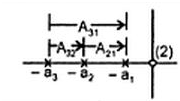
  1. In the given figure shows the pole “ zero plot , The Transfer function F(s) is

  2. A.
    (s-a1)(s-a2) (s-a3)
    B.
    (s+a1)(s+a2) (s+a3)
    C.
    s2/(s+a1)(s+a2) (s+a3)
    D.
    1/(s-a1)(s-a2) (s-a3)

    View Answer

    Workspace

    Discuss Discuss in Forum


  3. For the first order system having Transfer system 1/(1-sT),the unit impulse response is
  4. A.
    e "“t/T
    B.
    T e "“t/T
    C.
    (1/T) * e t/T
    D.
    T2 e "“t/T

    View Answer

    Workspace

    Discuss Discuss in Forum


  5. Signal flow graph is used to find _________
  6. A.
    Stability of the system
    B.
    Controllability of the system
    C.
    Transfer function of the system
    D.
    Poles of the system

    View Answer

    Workspace

    Discuss Discuss in Forum


  7. As compared to a Closed loop system an Open loop system is
  8. A.
    More stable as well as more accurate
    B.
    Less stable as well as less accurate
    C.
    More stable but less accurate
    D.
    Less stable but more accurate

    View Answer

    Workspace

    Discuss Discuss in Forum


  9. Phase margin of a system is used to specify
  10. A.
    Relative stability
    B.
    Absolute Stability
    C.
    Time Response
    D.
    Frequency response

    View Answer

    Workspace

    Discuss Discuss in Forum


  11. Gain cross - over frequency is defined as
  12. A.
    |G(jω)H(jω)|=1
    B.
    |G(jω)H(jω)|=0
    C.
    |G(jω)H(jω)|=∞
    D.
    |G(jω)H(jω)|=1/2

    View Answer

    Workspace

    Discuss Discuss in Forum


  13. Which one of the following is an example of open “ loop system
  14. A.
    A windscreen wiper
    B.
    Respiratory system of an animal
    C.
    A system for controlling anti-rocket missiles
    D.
    None of these

    View Answer

    Workspace

    Discuss Discuss in Forum


  15. The principles of Homogeneity & Superposition are applied to
  16. A.
    Linear Time Variant Systems
    B.
    Non - Linear Time Variant Systems
    C.
    Linear Time Invariant Systems
    D.
    Non - Linear Time Invariant Systems

    View Answer

    Workspace

    Discuss Discuss in Forum


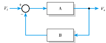
  17. What is the Voltage gain of the following arrangement

  18. A.
    (1+AB)/B
    B.
    B/ (1+AB)
    C.
    (1+AB)/A
    D.
    A/ (1+AB)

    View Answer

    Workspace

    Discuss Discuss in Forum


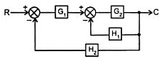
  19. The Transfer function C/R of the block diagram given below is

  20. A.
    G1+(G2/(1+G2H1+H2))
    B.
    G1 G2/(1+G1 H2 H1 H2)
    C.
    G1 G2/( G2H1+ G1 G2 H2+1)
    D.
    G1 G2/(1+G2 H1+ G1 H2)

    View Answer

    Workspace

    Discuss Discuss in Forum