Discussion :: Digital Electronics
-
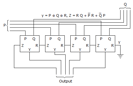
The circuit show in the figure has 4 boxes each described by inputs P, Q, R and outputs y, z with
Y = P ⊕ Q ⊕ R, Z = RQ + PR + QP The circuit act as a
|
A.
4 bit adder giving P + Q
|
|
B.
4 bit subtractor P - Q
|
|
C.
4 bit subtractor Q - P
|
|
D.
4 bit adder P + Q + R
|
Answer : Option B
Explanation :
No answer description available for this question.
Be The First To Comment


 Whatsapp
 Facebook

