Home / ECE / Network Analysis and Synthesis :: Section 7

ECE :: Network Analysis and Synthesis

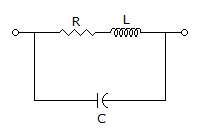
  1. The equivalent circuit of a resistor is shown in the given figure. The resistor will be non-inductive if
  2. A.
    B.
    C.
    L = CR2
    D.
    C = LR2

    View Answer

    Workspace

    Discuss Discuss in Forum


  3. For a series RLC circuit bandwidth is ω2 - ω1 = R/2L.

  4. A.
    True
    B.
    False

    View Answer

    Workspace

    Discuss Discuss in Forum


  5. If , the network has

  6. A.
    1 H inductor and 1 F capacitor in parallel
    B.
    1 H inductor and 1 F capacitor in series
    C.
    1 H inductor and 1 Ω resistor in series
    D.
    1 H inductor and 1 Ω resistor in parallel

    View Answer

    Workspace

    Discuss Discuss in Forum


  7. In figure, the voltage V1 = 4∠0 V. The source voltage V2 is

  8. A.
    8 - j8 volts
    B.
    4 - j4 volts
    C.
    8 - j4 volts
    D.
    8 - j16 volts

    View Answer

    Workspace

    Discuss Discuss in Forum


  9. A capacitor whose capacitance Ct = C0 (1- cos ωt) is fed by a sinusoidal voltage v = V0 sin ωt. The equation for current i is

  10. A.
    ω C0V0 cos ωt
    B.
    ω C0V0 sin ωt
    C.
    ω C0V0 (cos ωt - cos2 ωt)
    D.
    none of the above

    View Answer

    Workspace

    Discuss Discuss in Forum


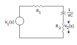
  11. Figure shows an RC circuit. The magnitude plot V2/V1
  12. A.
    will rise exponentially to R2/(R1 + R2) as ω → ∞
    B.
    will rise linearly to R2/(R1 + R2) as ω → ∞
    C.
    will decrease to zero as ω → ∞
    D.
    will rise 1 at ω = 0 and then decrease as ω → ∞

    View Answer

    Workspace

    Discuss Discuss in Forum


  13. Assertion (A): In a circuit having high inductance, reactive power may be more than apparent power.

    Reason (R): Reactive power = VI sin θ.

  14. A.
    Both A and R are true and R is correct explanation of A
    B.
    Both A and R are true and R is not the correct explanation of A
    C.
    A is true but R is false
    D.
    A is false but R is true

    View Answer

    Workspace

    Discuss Discuss in Forum


  15. A two branch parallel circuit has a 10 Ω resistance and 0.5 H inductance in one branch and a 100 μF capacitor in the second branch. It is fed from 100 V ac supply. At resonance, the source current is

  16. A.
    10 A
    B.
    1 A
    C.
    0.2 A
    D.
    0.05 A

    View Answer

    Workspace

    Discuss Discuss in Forum


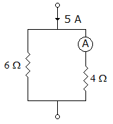
  17. In figure, A is ideal ammeter having zero resistance. It will read __________ ampere.
  18. A.
    2
    B.
    2.5
    C.
    3
    D.
    4

    View Answer

    Workspace

    Discuss Discuss in Forum


  19. Threshold of perception occurs at a current of about 1 mA.

  20. A.
    True
    B.
    False

    View Answer

    Workspace

    Discuss Discuss in Forum