Home / ECE / Network Analysis and Synthesis :: Section 10

ECE :: Network Analysis and Synthesis

  1. Impedance Z as shown in the given figure is

  2. A.
    j29 Ω
    B.
    j9 Ω
    C.
    j19 Ω
    D.
    j35 Ω

    View Answer

    Workspace

    Discuss Discuss in Forum


  3. A resistance R, inductance L and capacitance C are in series. The source frequency is adjusted to be equal to resonant frequency. The lower half power frequency is ω1. Another resistance R is added in series with the circuit. The new lower half power frequency will be

  4. A.
    ω1
    B.
    less than ω1
    C.
    more than ω1
    D.
    either more than ω1 or less then ω1

    View Answer

    Workspace

    Discuss Discuss in Forum


  5. The strength of controlled voltage source depends on

  6. A.
    value of current elsewhere in the circuit
    B.
    value of voltage elsewhere in the circuit
    C.
    value of current or voltage elsewhere in the circuit
    D.
    none of the above

    View Answer

    Workspace

    Discuss Discuss in Forum


  7. In figure, the value of R should be

  8. A.
    0.2 Ω
    B.
    0.1 Ω
    C.
    0.05 Ω
    D.
    0.1 Ω

    View Answer

    Workspace

    Discuss Discuss in Forum


  9. In figure the open circuit emf is

  10. A.
    15 V
    B.
    1.45 V
    C.
    1.475 V
    D.
    1.485 V

    View Answer

    Workspace

    Discuss Discuss in Forum


  11. In a practical current source, the load current

  12. A.
    is always equal to source current
    B.
    is always less than source current
    C.
    is always equal to or less than source current
    D.
    cannot be higher than source current

    View Answer

    Workspace

    Discuss Discuss in Forum


  13. If

  14. View Answer

    Workspace

    Discuss Discuss in Forum


  15. The pole zero diagram of an impedance Z has a pole at s = - 6 and zero at s = - 4 as shown in figure the constant multiplier k = 1. For a signal Is = cos 6t, the steady state voltage across Z is given in magnitude as under

  16. A.
    0.6
    B.
    0.84
    C.
    7.2
    D.
    none

    View Answer

    Workspace

    Discuss Discuss in Forum


  17. A resistor R of 1 Ω and two inductor L1 and L2 of inductances 1 H and 2 H respectively, are connected in parallel. At some time, the current through L1 and L2 are 1 A and 2 A, respectively. The current through R at time t = ∞ will be

  18. A.
    zero
    B.
    1 A
    C.
    2 A
    D.
    3 A

    View Answer

    Workspace

    Discuss Discuss in Forum


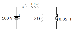
  19. In the circuit of figure the current through 5 Ω resistance at t = 0+ is
  20. A.
    0 A
    B.
    10 A
    C.
    6.67 A
    D.
    5.1 A

    View Answer

    Workspace

    Discuss Discuss in Forum