Home / ECE / Network Analysis and Synthesis :: Section 11

ECE :: Network Analysis and Synthesis

  1. In figure readings of the two voltmeters should be

  2. A.
    100 V on each meter
    B.
    200 V on each meter
    C.
    150 V on V1 and 50 V on V2
    D.
    50 V on V1 and 150 V on V2

    View Answer

    Workspace

    Discuss Discuss in Forum


  3. The internal impedance of a source is 3 + j 7 Ω. For maximum power transfer, load impedance should be

  4. A.
    3 + j 7 Ω
    B.
    3 - j 7 Ω
    C.
    7 + j 3 Ω
    D.
    7 - j 3 Ω

    View Answer

    Workspace

    Discuss Discuss in Forum


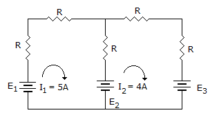
  5. In the circuit of figure, the current through battery E3 is
  6. A.
    4 A charging
    B.
    4 A discharging
    C.
    4 A charging or discharging depending on value of E3
    D.
    4 A charging or discharging depending on values of E1, E2, E3

    View Answer

    Workspace

    Discuss Discuss in Forum


  7. In the circuit of figure

  8. A.
    Va would always lag Vb
    B.
    Va would always lead Vb
    C.
    Va and Vb would always be in phase
    D.
    Va may lag or lead Vb

    View Answer

    Workspace

    Discuss Discuss in Forum


  9. Two capacitors of 16 μF each are connected in series. Another capacitor of 16 μF is connected in parallel with this combination. The total capacitance will be

  10. A.
    48 μF
    B.
    32 μF
    C.
    24 μF
    D.

    View Answer

    Workspace

    Discuss Discuss in Forum


  11. Assertion (A): Operator has a value 1 ∠ - 90° or 1 ∠ 90°.

    Reason (R): Operator 'a' has a value 1 ∠ 120°.

  12. A.
    Both A and R are true and R is correct explanation of A
    B.
    Both A and R are true and R is not the correct explanation of A
    C.
    A is true but R is false
    D.
    A is false but R is true

    View Answer

    Workspace

    Discuss Discuss in Forum


  13. The maximum current and voltage ratings for a 0.5 W, 10 kW resistor are

  14. A.
    7.07 mA and 70.7 V
    B.
    70.7 mA and 70.7 V
    C.
    0.707 mA and 70.7 V
    D.
    7.07 mA and 70.7 x 10³ V

    View Answer

    Workspace

    Discuss Discuss in Forum


  15. Figure shows a pole zero plot of I(s). The likely current response in time domain is

  16. A.
    i (t) = e-1 - e-3t
    B.
    i (t) = e-1 - 2e-2t
    C.
    i (t) = e-1 - e-2t
    D.
    i (t) = e-1 - e-4t

    View Answer

    Workspace

    Discuss Discuss in Forum


  17. A system has transfer function The dc gain is

  18. A.
    1
    B.
    2
    C.
    5
    D.
    10

    View Answer

    Workspace

    Discuss Discuss in Forum


  19. In a series RLC circuit, the current at resonance is I0 the total energy stored in the circuit at resonance is

  20. A.
    LI02
    B.
    2 LI02
    C.
    2 LI02
    D.
    0.5 LI2

    View Answer

    Workspace

    Discuss Discuss in Forum