Home / ECE / Network Analysis and Synthesis :: Section 14

ECE :: Network Analysis and Synthesis

  1. The nodal method of circuit analysis is based on

  2. A.
    KVLs, ohm law
    B.
    KCLs, ohm law
    C.
    KCLs, KVL
    D.
    KCL, KVL, ohms law

    View Answer

    Workspace

    Discuss Discuss in Forum


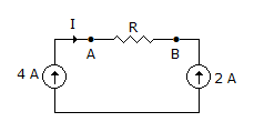
  3. In figure, the current I

  4. A.
    is 2 A from A to B
    B.
    is 2 A from B to A
    C.
    depends on the value of R
    D.
    none of the above

    View Answer

    Workspace

    Discuss Discuss in Forum


  5. Pico-farad is equal to

  6. A.
    10-6 farad
    B.
    10-12 farad
    C.
    10-3 farad
    D.
    10-9 farad

    View Answer

    Workspace

    Discuss Discuss in Forum


  7. A network has only independent current sources and resistance. If values of all resistors are doubled, the values of node voltages

  8. A.
    will become half
    B.
    will remain unchanged
    C.
    will become double
    D.
    cannot be determined unless circuit configuration and values of resistors are known

    View Answer

    Workspace

    Discuss Discuss in Forum


  9. Which of the following is/are correct? The circuit shown in the figure.

    1. is reciprocal
    2. has Z11 = 2, Z22 = 2
    3. has Z11 = 4, Z22 = 2
    4. has Z11 = 0, Z22 = 2
    Select the correct answer using the code given below:

  10. A.
    1 and 3
    B.
    1 and 2
    C.
    1 and 4
    D.
    3 only

    View Answer

    Workspace

    Discuss Discuss in Forum


  11. A sine wave of voltage varies from zero to maximum of 200V. How much is the voltage at the instant of 30° of the cycle?

  12. A.
    50 V
    B.
    82.8 V
    C.
    100 V
    D.
    173.2 V

    View Answer

    Workspace

    Discuss Discuss in Forum


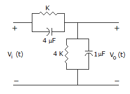
  13. In the figure shown, assume that all the capacitors are initially unchanged and Vi(t) = 10 U(t) volts then V0(t) is given by

  14. A.
    8 e-0.004t volts
    B.
    8 (j - e-0.004t) volts
    C.
    8 u(t) volts
    D.
    8 volts

    View Answer

    Workspace

    Discuss Discuss in Forum


  15. For the network in figure, the correct loop equation for loop 3 is

  16. A.
    -I1 + 4I2 + 11I3 = 0
    B.
    I1 + 4I2 + 11I3 = 0
    C.
    -I1 - 4I2 + 11I3 = 0
    D.
    I1 - 4I2 + 6I3 = 0

    View Answer

    Workspace

    Discuss Discuss in Forum


  17. Force = Electric intensity x current.

  18. A.
    True
    B.
    False

    View Answer

    Workspace

    Discuss Discuss in Forum


  19. In a R-L-C circuit at resonance is

  20. A.
    maximum in series resonance and minimum in parallel resonance.
    B.
    maximum in parallel resonance and minimum in series resonance
    C.
    minimum in both series and parallel resonances
    D.
    maximum in both series and parallel resonances.

    View Answer

    Workspace

    Discuss Discuss in Forum