ECE :: Exam Questions Paper
-
For the 8085 assembly language program given below, the content of the accumulator after the execution of the program is

-
Consider the following BJT circuit:
hie = 2 k ohm
hfe = 100
hre = 2.5 x 10⁻⁴
The value of Ri is : -
 . The signal is __________ .
 -
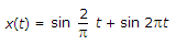
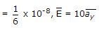
The electric field of uniform plane wave is given by E = 20 sin (2 p x 108t- pz)
 x + 20 cos (2 p x 108t - pz) y. The polarization of wave is
 -
A two port network shown below is external dc sources. The voltages and the currents are measured with voltmeters V1 V2 and ammeter A1 A2 (all assumed to be ideal), as indicated. Under following switch conditions, the readings obtained are:
(i) S1 - Open, S2 - Closed A1 = 0A, V1 = 4.5 V, V2 = 1.5 V, A2 = 1 A
(ii) S1 - Closed, S2 - Open A1 = 4A, V1 = 6 V, V2 = 6 V, A2 = 0 A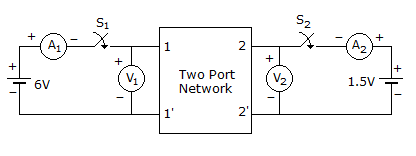
The z-parameter matrix for this network is -
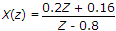
The Z-transform of a particular signal is given as X(Z) =
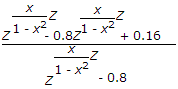 where
where 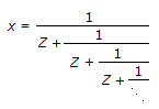
This system after practical implementation will be -
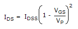
The JFET in the circuit shown in figure has an IDSS = 10 mA and Vp = -5 V. The value of the resistance Rs for a drain current IDS = 6.4 mA is (select the nearest value)

-
In the circuit s closed for a long time and steady state is reached. s is opened at t = 0+ Determine current through
 resistor.
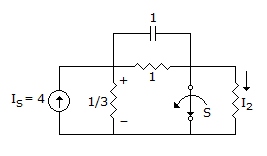
-
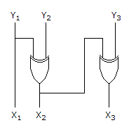
The logic circuit given below converts a binary code y1 y2, y3 into


 Whatsapp
 Facebook


 .
.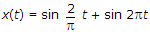
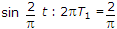
 for periodicity
  should be a rational number.
  not a rational number.


 = 0.8
= 0.8  = 0.8 - 1 = - 0.2
 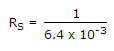 = 0.156 x 103 = 156 Ω.
 A
A  A
A  = 1 A.
 = 3
= 3  =
= Downwards