GATE 2017-2018 :: GATE ECE
-
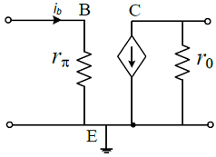
The current ib through the base of a silicon npn transistor is 1 + 0.1 cos(10000 π t) mA. At 300 K, the rπ in the small signal model of the transistor is
-
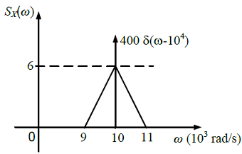
The power spectral density of a real process X(t) for positive frequencies is shown below. The values of E[X2(t)] and E[X(t)] , respectively, are
- In a baseband communications link, frequencies upto 3500 Hz are used for signaling. Using a raised cosine pulse with 75% excess bandwidth and for no inter-symbol interference, the maximum possible signaling rate in symbols per second is
-
The electric field of a uniform plane electromagnetic wave in free space, along the positive x direction, is given by
 . The frequency and polarization of the wave, respectively, are
 -
Consider the given circuit.
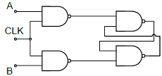 In this circuit, the race around
 - The output Y of a 2-bit comparator is logic 1 whenever the 2-bit input A is greater than the 2-bit input B. The number of combinations for which the output is logic 1, is
-
The i-v characteristics of the diode in the circuit given below are
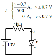 The current in the circuit is
 -
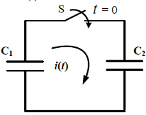
In the following figure, C1 and C2 are ideal capacitors. C1 has been charged to 12 V before the ideal switch S is closed at t = 0. The current i(t) for all t is
- The average power delivered to an impedance (4 - j3) Ω by a current 5cos(100π t + 100) A is
- The unilateral Laplace transform of f(t) is 1/(s2 + s + 1). The unilateral Laplace transform of t f (t) is

 Whatsapp
 Facebook


