Home / ECE / Analog Electronics :: Section 7

ECE :: Analog Electronics

  1. It is desired to reduce distortion in a CE amplifier circuit. We should

  2. A.
    reduce emitter current
    B.
    reduce collector current
    C.
    reduce ac base voltage
    D.
    reduce base emitter voltage

    View Answer

    Workspace

    Discuss Discuss in Forum


  3. In the circuit of figure β = 50 and VBE = 0.5 V. The quiescent value of base current IB is

  4. A.
    about 28 μA
    B.
    about 28 mA
    C.
    about 0.28 μA
    D.
    about 2.8 A

    View Answer

    Workspace

    Discuss Discuss in Forum


  5. For a push pull circuit the most favoured biasing method is

  6. A.
    self bias
    B.
    emitter bias
    C.
    diode bias
    D.
    collector bias

    View Answer

    Workspace

    Discuss Discuss in Forum


  7. In feedback amplifier the closed loop gain is nearly independent of open loop gain and depends only on the feedback factor.

  8. A.
    True
    B.
    False

    View Answer

    Workspace

    Discuss Discuss in Forum


  9. In a N-P-N transistor, when emitter junction is forward biased and collector junction is reverse biased, the transistor will operate in

  10. A.
    active region
    B.
    saturation region
    C.
    cut of region
    D.
    inverted region

    View Answer

    Workspace

    Discuss Discuss in Forum


  11. A feedback network to be used with an amplifier to provide oscillation is tested and found to give an output of 0.124 V with a 0.5 V input. What percentage negative feedback should be introduced to the amplifier so that linear oscillations result?

  12. A.
    1.25%
    B.
    2.50%
    C.
    -1.25%
    D.
    -2.5%

    View Answer

    Workspace

    Discuss Discuss in Forum


  13. The advantage of Weinbridge oscillator over the phase shift oscillator is that oscillator the frequency may be varied over a range of

  14. A.
    1 : 2
    B.
    1 : 3
    C.
    1 : 5
    D.
    1 : 10

    View Answer

    Workspace

    Discuss Discuss in Forum


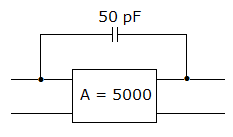
  15. In figure the input and output Miller capacitances are

  16. A.
    0.25 μF each
    B.
    500 pF each
    C.
    0.25 μF and 500 pF respectively
    D.
    500 pF and 0.25 μF respectively

    View Answer

    Workspace

    Discuss Discuss in Forum


  17. An inverting amplifier has R1 = 10 kΩ, and Rf = 150 kΩ then the O/P voltage, if input voltage Vi = 1 volt.

  18. A.
    -15 V
    B.
    -10 V
    C.
    15 V
    D.
    -14 V

    View Answer

    Workspace

    Discuss Discuss in Forum


  19. Figure uses 10 V zener diode. The minimum and maximum current through series resistance are

  20. A.
    10 mA and 30 mA
    B.
    20 mA and 40 mA
    C.
    0 and 30 mA
    D.
    0 and 40 mA

    View Answer

    Workspace

    Discuss Discuss in Forum