Home / ECE / Digital Electronics :: Section 12

ECE :: Digital Electronics

  1. In 8085, to disable the whole interrupt system (except TRAP)

  2. A.
    the DI instruction may be used
    B.
    the DO instruction may be used
    C.
    the INTERRUPT instruction may be used
    D.
    the El instruction may be used

    View Answer

    Workspace

    Discuss Discuss in Forum


  3. The reason for glitches on the outputs of decoding gates on a synchronous counter is

  4. A.
    FFs changing states together
    B.
    FFs changing states one at a time
    C.
    AND gates not functioning properly
    D.
    none of the above

    View Answer

    Workspace

    Discuss Discuss in Forum


  5. EEPROM is also known as

  6. A.
    UVPROM
    B.
    EAPROM
    C.
    both UVPROM and EAPROM
    D.
    none of the above

    View Answer

    Workspace

    Discuss Discuss in Forum


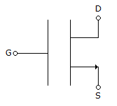
  7. The MOS symbols shown indicates:

    1. that it is depletion type
    2. that it is enhancement type
    3. that it is n channel
    4. that it is p channel
    5. that electrons flow from D to S
    6. that holes flow from D to S
    The only true statements are

  8. A.
    1, 3, 6
    B.
    2, 4, 6
    C.
    1, 3, 5
    D.
    2, 3, 6

    View Answer

    Workspace

    Discuss Discuss in Forum


  9. As compared to TTL, CMOS logic has

  10. A.
    higher speed of operation
    B.
    higher power dissipation
    C.
    smaller physical size
    D.
    all of the above

    View Answer

    Workspace

    Discuss Discuss in Forum


  11. Decimal number 5436 when converted into 9's complement will become

  12. A.
    4356
    B.
    4653
    C.
    4563
    D.
    4655

    View Answer

    Workspace

    Discuss Discuss in Forum


  13. What is output 'Z' of an EX-OR gate, whose all inputs are set at A?

  14. A.
    Z = A
    B.
    Z = 1
    C.
    Z = 0
    D.
    Z = A

    View Answer

    Workspace

    Discuss Discuss in Forum


  15. Minimum number of J-K flip-flop needed to construct a BCD counter is

  16. A.
    2
    B.
    3
    C.
    4
    D.
    5

    View Answer

    Workspace

    Discuss Discuss in Forum


  17. The following switching functions are to be implemented using a decoder

    1. f1 = ∑m (1, 2, 4, 8, 10, 14)
    2. f2 = ∑m (2, 5, 9, 15)
    3. f3 = ∑m (2, 4, 5, 6, 7)
    The minimum configuration of decoder is

  18. A.
    2 to 4 line
    B.
    3 to 8 line
    C.
    4 to 16 line
    D.
    5 to 32 line

    View Answer

    Workspace

    Discuss Discuss in Forum


  19. For the logic circuit of the given figure the simplified Boolean expression is

  20. A.
    A ⊕ B
    B.
    A + B
    C.
    AB
    D.
    A + B

    View Answer

    Workspace

    Discuss Discuss in Forum