Home / ECE / Digital Electronics :: Section 23

ECE :: Digital Electronics

  1. TTL XOR gate is very suitable as LCO driver.

  2. A.
    True
    B.
    False

    View Answer

    Workspace

    Discuss Discuss in Forum


  3. A typical microcomputer has 65, 536 registers in its memory. It will be specified as

  4. A.
    65.536 memory
    B.
    65.536 K memory
    C.
    64 K memory
    D.
    8 K memory

    View Answer

    Workspace

    Discuss Discuss in Forum


  5. A function table is required in very large numbers the memory most switched for this purpose would be

  6. A.
    ROM
    B.
    PROM
    C.
    EPROM
    D.
    EAROM

    View Answer

    Workspace

    Discuss Discuss in Forum


  7. What kind of signal does the times produce?

  8. A.
    Single pulse
    B.
    Square wave
    C.
    Continuous pulse
    D.
    No signal

    View Answer

    Workspace

    Discuss Discuss in Forum


  9. Assertion (A): A presettable counter can be preset to any desired starting point

    Reason (R): The maximum frequency of a ripple counter depends on the modulus.

  10. A.
    Both A and R are correct and R is correct explanation of A
    B.
    Both A and R are correct but R is not correct explanation of A
    C.
    A is true, R is false
    D.
    A is false, R is true

    View Answer

    Workspace

    Discuss Discuss in Forum


  11. A digital clock uses __________ chip

  12. A.
    SSI
    B.
    LSI
    C.
    VLSI
    D.
    MSI

    View Answer

    Workspace

    Discuss Discuss in Forum


  13. The contents of stack location 2109 H after the call operation will be

  14. A.
    00001111
    B.
    01010101
    C.
    00100000
    D.
    00100010

    View Answer

    Workspace

    Discuss Discuss in Forum


  15. Which of the following conversion is incorrect?

  16. A.
    1111101112 = 7678
    B.
    110110103 = 6658
    C.
    1011.11112 = 13.748
    D.
    10101.112 = 26.58

    View Answer

    Workspace

    Discuss Discuss in Forum


  17. In a flip-flop with RS latch a high S and a low R set the output to __________ and a low S and a high R set the output __________ .

  18. A.
    low, low
    B.
    high, high
    C.
    low, high
    D.
    high, low

    View Answer

    Workspace

    Discuss Discuss in Forum


  19. For the logic circuit shown in figure, the simplified Boolean expression for the output Y is
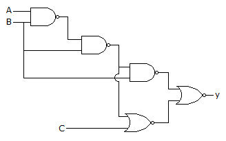
  20. A.
    A + B + C
    B.
    AB
    C.
    B
    D.
    C

    View Answer

    Workspace

    Discuss Discuss in Forum